the knotnet

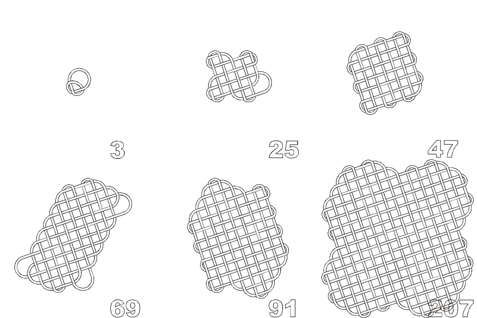
Grid Build Geometry, Flash vectors in gif animations, 2002

and the "intra"

a brief background
Genesis Sequence, Flash Vectors in gif animation, 2012


  • The circuit grid for building knots was fully developed by 1967.
  • An awareness of electronic circuitry and Systemic Painting was at first combined with performance art for readings ( alpha-bet , 1967 at St. Marks Church) and live set-ups (Members Show, MUSEUM, 1968).
  • Outreach to the Experiments in Art and Technology (EAT) program was also made.
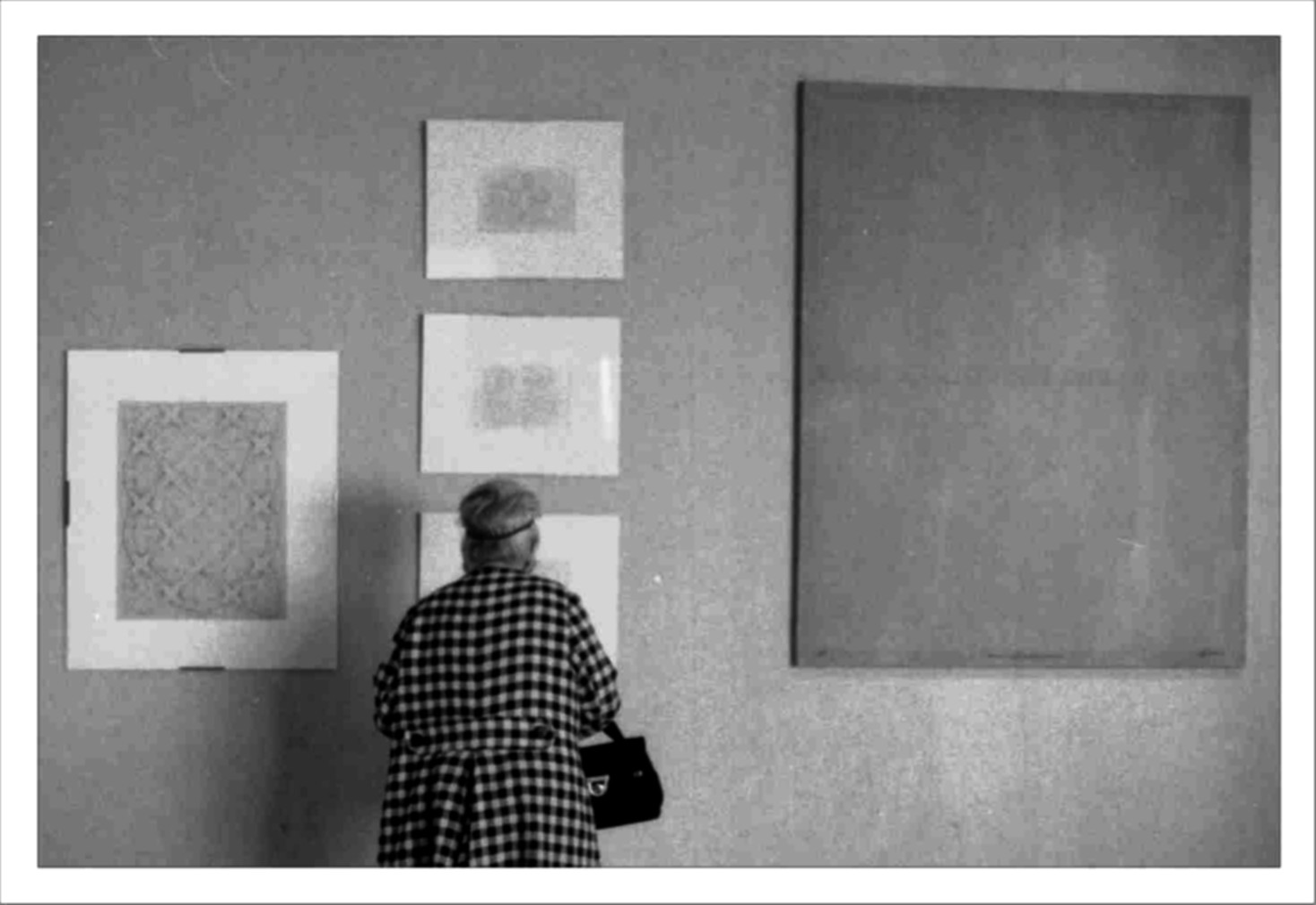
  • This produced the first sequential knots and once a way was developed to put the grid on canvas the systemic was replaced by a brief period of decorative interweave patterns (Marist Show, 1972 - images to right).
  • Pure digital art replaced artifacts using Autocad in a PCs Limited computer (first Dell) in 1982 and there were no public showings after that.
Gallery Art, 1972

First Gallery Show, Marist College, 1972
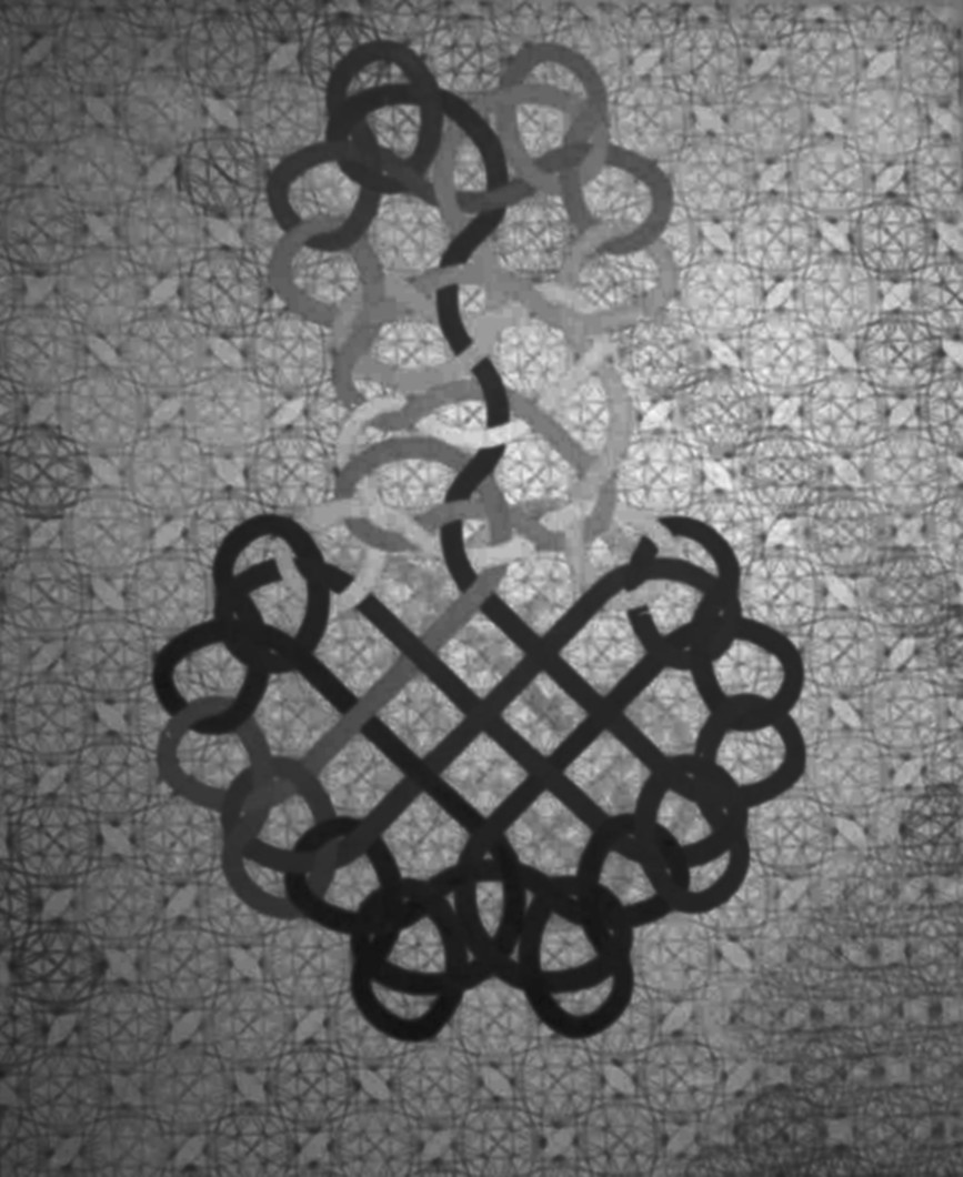

Venus Rising, 1971
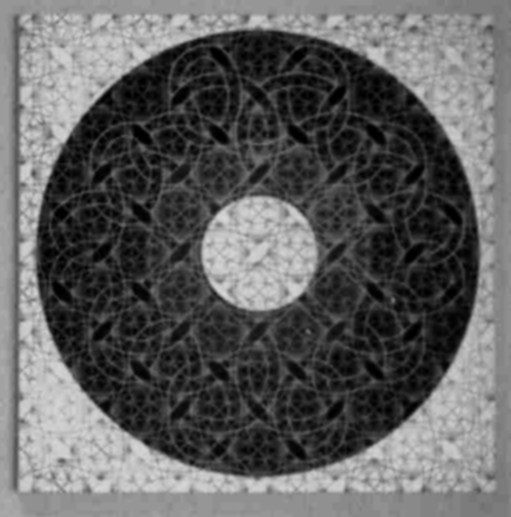

Celtic Circle, 1971
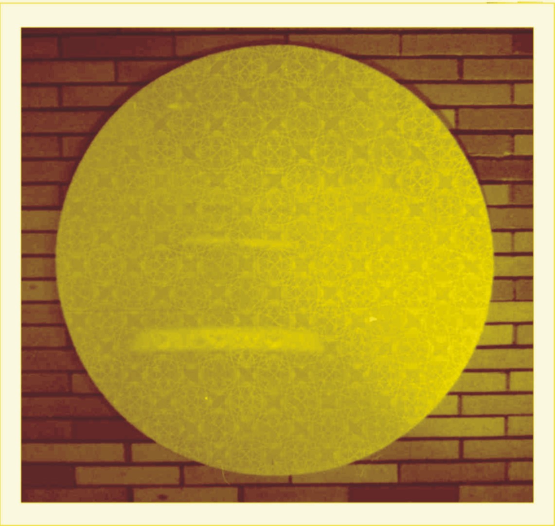

Yellow Plexi, 1971
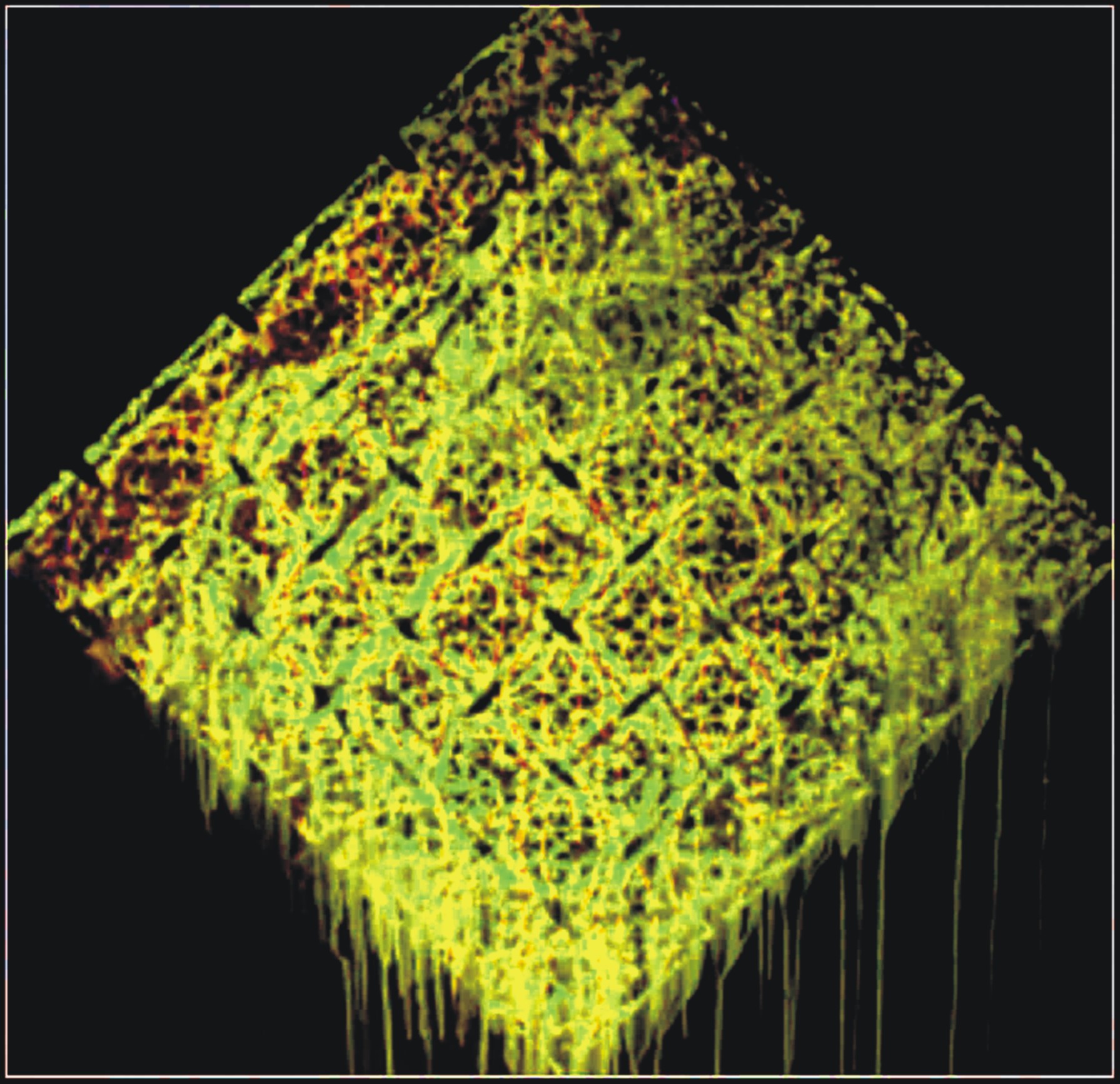

Monoprint Glass, 1967-1971


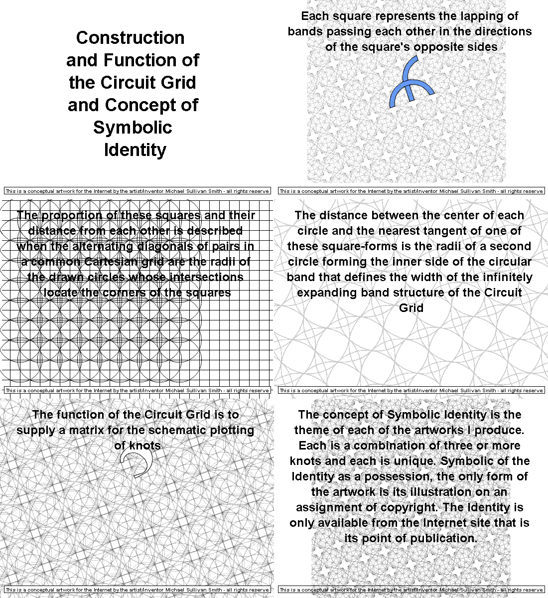
the concept is that the iterative repetition of geometry defined by the grid background of this page and the animation at the top that shows how it is produced has the Infra as a modular element; a slice of this geometry; as tiles of a grid that selected shapes fit like puzzle pieces to form knots.

the toolkit

The Works shown above, made from 1967 to 1998, were created on knot grids tiled at forty-five and ninety degree angles. The twenty-two and a half degree format of the tool kit was adopted to be aestheticly identifiable with a digital art as it was less inclined to the moire problems of CRT screens.

The image below is of an svg file containing the basic elements proved out in the creation of every knot in the Genesis Sequence. The shapes are on the left and the units for growing the grid are to the right. Clicking the mouse on this graphic opens the actual svg image on its own page. Right clicking on this svg image and selecting "Save page as..." copies the svg file into your computer.

Then download Inkscape (free shareware... direct link). Import the saved svg file into Inkscape, Ungroup the image to separate the elements, and you're ready to make knots.

The shapes on the right are the linear components: the shapes; the movements; of a knot.

The grid modules across the top are the minimum tile complexity that butt up against each other to make what is shown below them and on the background of this page. They and their grouping below them can be duplicated, built upon and combined ad infinitum from this one page of elements.

In the space below is a canvas that allows you to examine the svg by simply using your mouse wheel to zoom in and your left button to drag the image around.


working with the toolkit

This toolkit is the base for your own construction file. In Inkscape make two layers and put the grid components on the lowermost of the two. The linear components (and sample knot) stay on the top layer.

Lock the lower grid layer. Move the sample knot on the upper active layer into a matching position on the grid. The crossings will only match their correct positioning when this knot matches this size grid. The sample knot is on this page only to provide an exercise for using the layers feature of Inkscape and it can be deleted after serving this purpose.

All the knots that match this size grid have already been constructed so the grid will have to be expanded. Move all the top layer components away from the page area, lock their layer, unlock the grid layer and expand the grid by either copying the larger combination of modules and butting them against eachother or use the base module to add row by row.

When the grid has been sufficiently expanded, group the modules, lock the grid layer, unlock the top layer, and begin to construct a knot by copying components outside of the grid area, moving the copied component into the grid area and carefully registering it to its corresponding lines of the grid.

As the knots become more complex it will be handy to create some modular combinations of components to add to your personal toolkit.


The Open Source Plan

Open source design, proofing, and even decision on the next additions to the sequence brings a competitive element to this concept. Those contributing a knot and those that almost did are recognized.

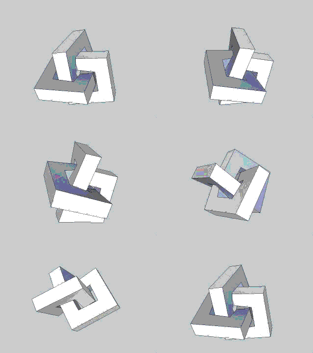
Only knots next in the sequence are accepted for certification. All knots deemed the special property of their creator while knots capable of interlinking and used for components of combination knots serve to rapidly increase the count of artworks in the product line . Operations are of a distributive review format totally open to anyone on the Internet. They accept designs, certify their place in the sequence, and reach by consensus the next to be designed in the sequence. The first six (five plus the winner) to respond with a submission get to have their signature on the new addition's entry into the sequence.

A valuation system that rewards all those that participate is to support this and even more complex functions that involve acquisition and profit.


The Great Knot, April 27, 2011


Michael Sullivan Smith, 2015
Click on animation to open parent web site greatknot.com in new browser window